PiSeg Arduino Project
View the sketch for this project itself, along with the Fritzing file, in my GitHub repository.
This simple sketch displays the first 8 thousand or so digits of PI on a 7 segment LED from Radioshack. The LED display is done nicely with a byte encoded segment value, where each bit turns a segment on or off. Below is a labeled diagram of the segments themselves:

Using the above diagram it is easy to see how we derive the values. The following illustrates computing the value for the digit 6:
A: 0 B: 0 C: 1 D: 1 E: 1 F: 1 G: 1
Compounding the above in order from segment A through G we get 0011111, which in base 10 we can write as 95. A simple way to do this conversion is using the Python interpreter to convert a string representation of the binary value to a base 10 integer using int('0011111', 2) and noting the return value is 95.
In the sketch, I create an array of bytes to hold the values for the digits 0-9, so looking up a digit is as easy as looking up the value at the digit's index into the array. So for digit 3 we would look up index 3. We can then use the handy readByte function to read a byte at a time, and turn the segment of the LED on or off depending on the bit value. Strangely, Arduino appears to reverse the order of the bits as you read them from the byte. So our above digit 6 would be read in order 1111100. To fix this, instead of reversing the byte and then reading bits from it, I reverse the order in which I apply the bit values to the segments, starting at the end and working backward to the beginning.
The digits of PI are stored in an included header file that defines the actual values into read-only PROGMEM. The sketch then reads the current digit of PI out of the PROGMEM array. I think using PROGMEM for this is a nice example of the kinds of data one would store into read-only memory.
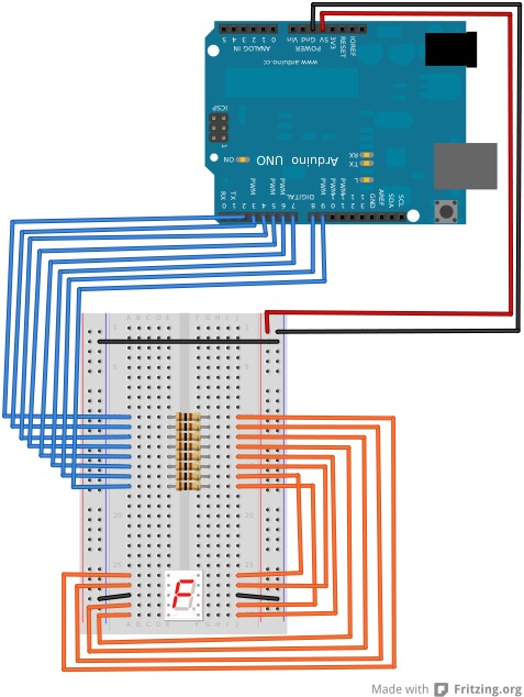
Below is a Fritzing diagram of the prototype (might have obsessed a little on this one):
